
How to Match a Pressure Switch to a Hydraulic System
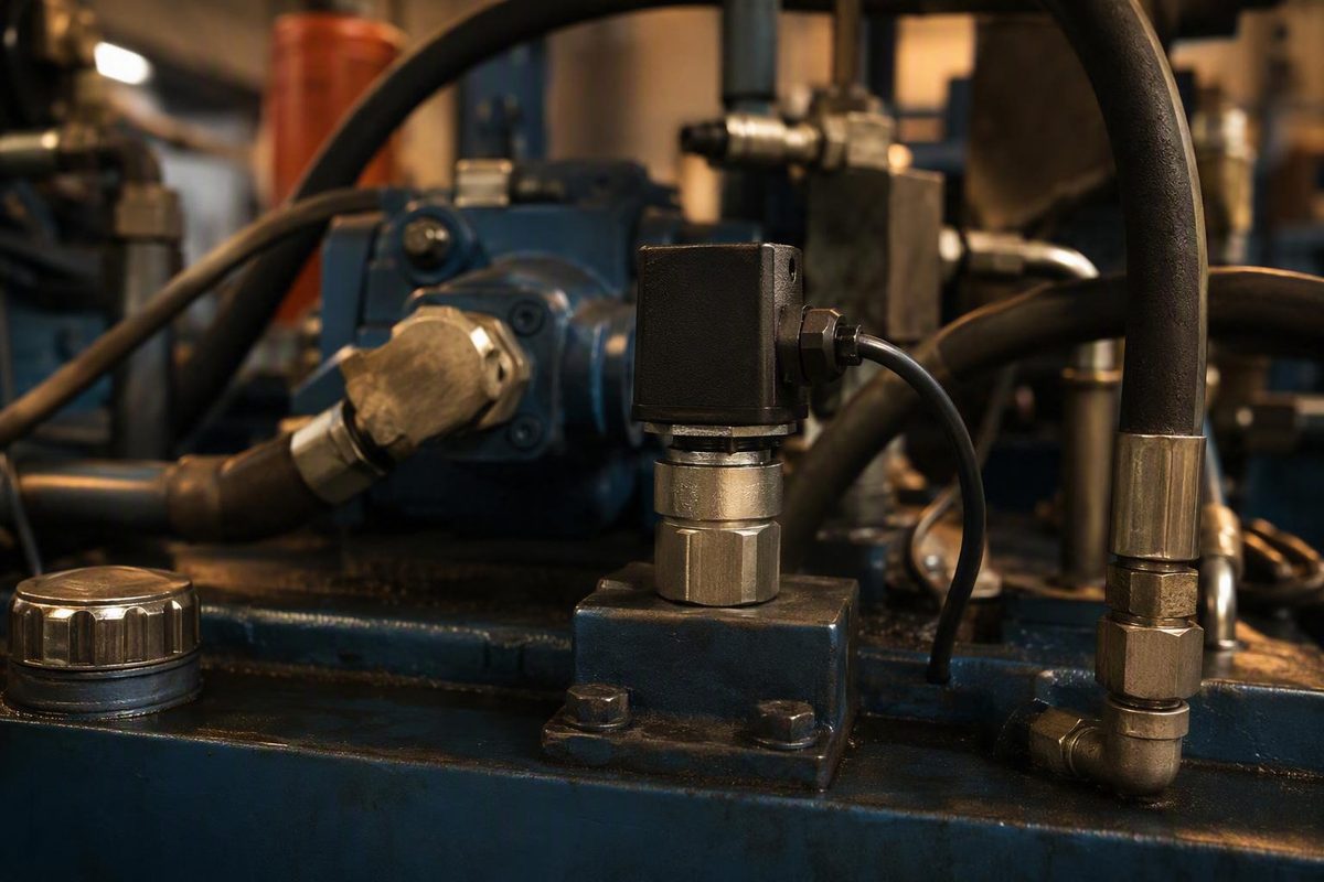
A hydraulic pressure switch cannot be selected safely or reliably from its PSI range alone. The switch must trip and reset at the required pressures, remain within every applicable pressure limit, connect correctly to the hydraulic circuit, provide a compatible electrical output, and tolerate the fluid and operating environment.
Treat this article as a requirements-gathering and preliminary screening guide—not as final engineering approval for a particular machine. Begin by defining the control function and required pressure behavior. Then distinguish the adjustment range from continuous-pressure, overpressure, and burst ratings. Before purchase or substitution, verify every requirement against the current manufacturer documentation for the exact part number.
What a hydraulic pressure switch does
A hydraulic pressure switch is a threshold-operated device. When pressure reaches or crosses a specified point, the device changes an electrical contact or electronic output from one state to another.
The basic operating sequence is:
- Hydraulic pressure reaches the pressure port.
- Pressure acts on a sensing element.
- The sensing element moves or produces an electronic response.
- That response operates contacts or changes an electronic output.
- The connected control system interprets the new state as a pressure condition.
Mechanical switches may use a piston or diaphragm to operate snap-action contacts. Electronic or solid-state models use electronic sensing and may add programmable set points, displays, or configurable outputs. Nason, for example, describes hardened-steel pistons in some high-pressure designs and elastomer diaphragms in low-pressure families, demonstrating why internal construction must be checked at model level rather than inferred from the product category. Nason distinguishes these mechanical constructions from solid-state pressure switches.
A simplified functional diagram looks like this:
Hydraulic circuit
       │
       ▼
┌─────────────────┐
│  Pressure port  │
└────────┬────────┘
         ▼
┌─────────────────┐
│ Sensing element │  Piston, diaphragm, or electronic sensor
└────────┬────────┘
         ▼
┌─────────────────┐
│ Set-point or    │  Spring/adjustment mechanism where fitted,
│ signal mechanism│  or a programmed electronic threshold
└────────┬────────┘
         ▼
┌─────────────────┐
│ Contacts or     │  NO, NC, SPDT, or electronic output
│ electronic output│
└────────┬────────┘
         ▼
┌─────────────────┐
│ Electrical      │  Terminals, leads, DIN-style plug,
│ connection      │  or equipment-specific receptacle
└─────────────────┘
Typical high-level functions include:
- High- or low-pressure indication
- Alarm input
- Permissive or interlock
- Pump-control signal
- Valve-control signal
- Shutdown input
- Confirmation that clamping, braking, lubrication, or actuation pressure has been established
A pressure switch ordinarily provides a discrete state: pressure is above or below a threshold, or the output is open or closed. It does not normally tell a controller whether the system is at 800, 1,000, or 1,200 PSI. Continuous pressure information generally requires a pressure transducer or transmitter.
Do not infer exact behavior from a label such as “normally open.” Define the reference condition: zero pressure, pressure below the set point, equipment de-energized, or another documented state. Powered electronic outputs may also have specific behavior during startup, loss of supply, or an internal fault.
The exact construction determines how the device responds, whether it requires electrical power, how it must be wired, and what load or controller input it can serve. Confirm those details for the selected part number.
Set point, reset point, and deadband explained
A pressure switch usually has at least two relevant operating points:
- Rising-pressure set point: the pressure at which the monitored contacts or output change state while pressure is increasing.
- Falling-pressure reset point: the pressure at which the contacts or output return to their previous state while pressure is decreasing.
For the common rising-trip, falling-reset test discussed here:
Observed deadband = rising-pressure trip point − falling-pressure reset point
If a switch trips while pressure is rising at 1,000 PSI and resets while pressure is falling at 900 PSI:
1,000 PSI − 900 PSI = 100 PSI observed deadband
The appropriate separation depends on the application.
For an alarm, the reset point determines when the indication clears. For pump control, it helps establish the pressure movement required before the command reverses. A switch can therefore have an acceptable trip range but still be unsuitable because its reset behavior would cause excessive cycling or an unacceptable process swing.
Deadband, differential, hysteresis, cut-in, and cut-out may refer to different quantities or directions in different documents. One datasheet may define differential as the gap between cut-in and cut-out; another may use the term for a separately adjustable value. Use the definitions and test direction stated for the exact switch.
Retailer listings illustrate this variability but should not be treated as validated engineering specifications. One catalog lists a Delta PS-3000 with a 50–150 PSI reset differential and a Magnaloy PS-400-115 with an approximately 300 PSI reset differential at a stated 1,125 PSI setting. These examples show why reset behavior must be checked separately; they do not establish interchangeability or suitability. The catalog attributes those figures to the named models.
Set-point adjustment and differential adjustment are separate capabilities:
- A fixed switch may allow neither to be changed.
- An adjustable switch may permit only the primary set point to be changed.
- One adjustment may move both operating points.
- Some designs may provide a separate differential adjustment.
- Electronic models may permit independent programming within documented constraints.
Never assume that changing one adjustment leaves the other operating point unchanged. After any authorized adjustment, verify and record both rising and falling operation.
Do not confuse switching range with pressure limits
Pressure-switch listings often display several large pressure values together, although the numbers describe different conditions.
Separate at least these specifications:
- Desired switching point: where the application needs the output to change
- Adjustment or set-point range: where the switch can be configured to operate
- Normal operating pressure: pressure expected in routine service
- Maximum continuous pressure: the highest pressure permitted continuously under stated conditions
- Transient pressure: short-duration pressure excursions expected at the sensing point
- Proof or overpressure rating: a manufacturer-defined survival or test limit under specified conditions
Duration, cycle count, temperature, media, and acceptance criteria must come from the applicable documentation.
An adjustment range identifies where a switch may be set. It does not necessarily state what pressure the device may withstand continuously. Conversely, an overpressure or burst figure does not expand the allowable set-point range.
For example, Anfield lists its KAPS/KAPF hydraulic pressure switch with a 350–3,200 PSI adjustment range and 15,000 PSI maximum overpressure. Those are separate specifications: the overpressure value does not make 15,000 PSI an allowable switching point or normal operating pressure. Anfield lists the adjustment and overpressure figures separately.
Retailer labels can be ambiguous. A category table may show “static” and “dynamic” values without adequately defining duration, cycle conditions, temperature, or the assembly to which each value applies. Do not automatically reinterpret those terms as continuous, proof, or burst ratings.
The available market also spans widely different duties. Catalog filters include set points from low single-digit PSI through several thousand PSI, while a specialized distributor listing advertises a 1,000–10,000 PSI range for an in-line Power Team model. That breadth does not establish suitability for any particular application. Direct Pneumatics lists the specialized model alongside lower-range hydraulic switches.
Pressure comparison box
Complete this comparison before approving a candidate:
| Pressure field | Application requirement | Candidate-switch specification | Evidence or confirmation |
|---|---|---|---|
| Desired rising trip pressure | Machine requirement/datasheet | ||
| Expected falling reset pressure | Datasheet or controlled verification | ||
| Required deadband or differential | Datasheet | ||
| Normal minimum pressure | Machine documentation | ||
| Normal maximum pressure | Machine documentation | ||
| Expected transient pressure | System analysis or measurement | ||
| Maximum continuous rating | Exact switch datasheet | ||
| Proof or overpressure rating | Datasheet and stated definition | ||
| Burst rating | Datasheet and stated definition | ||
| Applicable temperature and fluid | Machine and switch documentation |
Avoid selecting a switch merely because the desired setting touches an advertised range boundary. Confirm set-point tolerance, reset behavior, repeatability, temperature conditions, and every relevant pressure limit. If the required information is absent, treat the candidate as unresolved rather than compatible.
Fixed, adjustable, mechanical, or electronic?
The appropriate switch type depends on the required function, control architecture, and model-level specifications. No technology is universally faster, more accurate, or more durable.
Fixed or factory-preset switches
A fixed switch may suit a machine that requires one predetermined threshold and has compatible tolerance and reset requirements. A factory preset can also reduce unauthorized field changes, but “fixed” does not mean that its setting is correct for every machine.
Do not assume a switch is adjustable because it has a removable cover, threaded hardware, or a visible fastener. The hardware may retain or seal the assembly. Attempting to adjust a fixed design can damage it or invalidate its specified behavior.
Adjustable mechanical switches
An adjustable mechanical switch may be useful when the required threshold must be set within a documented range. Before selection, determine:
- Which operating point can be adjusted
- The permitted adjustment range
- Whether adjustment moves the trip point, reset point, or both
- Whether differential is fixed or separately adjustable
- What verification equipment is required
- Whether adjustment requires resealing
- Which tolerance and repeatability limits apply afterward
An adjustable set point is not the same as an independently adjustable differential.
Electromechanical switches
Electromechanical designs use a physical sensing element and moving contacts. Depending on the model, the sensing element may be a diaphragm or piston, and the electrical interface may provide normally open, normally closed, or changeover contacts.
Mechanical contacts do not automatically have adequate capacity for a proposed circuit. Voltage, current, load type, inrush, switching frequency, and other circuit requirements must be checked against exact documentation. If that information is incomplete, refer the circuit decision to qualified electrical or control-system personnel.
Electronic or solid-state switches
Electronic pressure switches use a powered sensor and circuitry to evaluate pressure. Depending on the model, they may offer:
- A display
- Programmable thresholds
- More than one switching output
- Configurable output logic
- Diagnostic indications
- Protection against unintended setting changes
Their selection introduces additional questions:
- What supply voltage is required?
- Is the output a relay, transistor, open collector, sourcing output, or sinking output?
- What is the output-current limit?
- Is the controller input compatible?
- What is the documented output state during startup or loss of supply?
- How are settings secured?
- Which environmental and electromagnetic conditions are permitted?
Compare documented set-point tolerance, repeatability, response definition, temperature drift, cycle rating, power requirements, and output type for the particular models. General technology comparisons are not a substitute for these specifications.
Switch, transducer, or both?
Use this decision framework:
Does the controller need a continuous pressure value?
│
├─ No
│  └─ Is the threshold predetermined and not intended for field change?
│     ├─ Yes → Consider a fixed or factory-preset switch.
│     └─ No  → Consider an adjustable mechanical or electronic switch.
│
└─ Yes
   └─ Is continuous pressure feedback the only required function?
      ├─ Yes → Consider a pressure transducer or transmitter.
      └─ No  → Consider a transducer plus a separate discrete switch
               if the documented control architecture requires both.
A switch supplies an on/off state, while a transducer converts pressure into a continuous electrical signal. A system may use a transducer for monitoring or control and a separate switch for a distinct threshold input.
The hydraulic pressure switch selection checklist
A sound screening process begins with a written requirement. Do not start with thread size, brand familiarity, or the widest available PSI range.
1. Define the function
State what the signal must do:
- Annunciate low or high pressure
- Permit or prevent another operation
- Provide a pump-control signal
- Provide a valve-control signal
- Supply a shutdown input
- Confirm that required process pressure has been established
Also document the required response to a broken wire, loss of electrical power, or failure to change state. These are system-design questions, not properties that can be inferred from “NO” or “NC.”
2. Define rising and falling behavior
Record:
- Whether the relevant event occurs on rising or falling pressure
- Desired trip pressure
- Acceptable trip tolerance
- Desired or acceptable reset pressure
- Permissible deadband
- Whether adjustment is required
- Who may adjust the device
- How the final setting will be verified
A description such as “1,000 PSI switch” is not a complete switching requirement.
3. Document every system-pressure condition
List normal minimum and maximum pressure, startup and shutdown conditions, trapped-pressure conditions identified by the machine documentation, expected transients, and pressure at the actual sensing point.
Compare these values with each separately defined switch rating. Do not use proof, overpressure, static, dynamic, or burst capacity as the normal operating range. If a term is not defined well enough to support comparison, ask the manufacturer.
4. Verify fluid and wetted-material compatibility
“Hydraulic fluid” is too broad for final approval. Identify:
- Exact fluid and formulation
- Relevant additive package
- Operating and startup temperatures
- Potential contamination or water content
- Wetted metals
- Elastomers and seals
- Cleaning or flushing chemicals that may contact the switch
A catalog fluid filter can identify candidates, but it does not prove compatibility with every oil, synthetic fluid, water-glycol formulation, phosphate ester, additive, or seal material.
5. Match the port and sealing method
Record the thread standard and sealing method. Catalogs include NPT, BSPP, BSPT, metric, and SAE straight-thread categories, while specialized listings also show NPTF connections. Similar appearance is not proof of interchangeability.
Check:
- Nominal port size
- Thread standard and pitch
- Tapered or straight form
- Male or female connection
- O-ring, bonded seal, thread sealant, or other sealing method
- Port material
- Required installation procedure
- Available clearance and support
Catalog filters can reveal possible categories but do not prove that every selected attribute is available together in one model. McMaster-Carr’s catalog illustrates the breadth of fluid, thread, set-point, connection, and environment filters.
Do not derive installation torque from thread size alone. Obtain the switch instructions and the machine-port requirements.
6. Define contact form and fault state
Possible arrangements include:
- Normally open
- Normally closed
- SPDT or changeover
- One or more electronic outputs
Define “normal” explicitly. For example:
With the machine de-energized and hydraulic pressure below the specified threshold, terminals X and Y shall be closed.
For an electronic switch, document the required output type and controller-input logic. Treat behavior under wire break, short circuit, or loss of supply as an unresolved design question unless the device and controller documentation explicitly define it.
7. Match the electrical circuit
Verify:
- AC or DC operation
- Supply voltage, if the device is powered
- Contact or output voltage rating
- Switching or output current
- Load type
- Inrush or other starting conditions
- Switching frequency
- Any documented external circuit requirements
- Conductor, grounding, and shielding requirements
Do not assume voltage compatibility proves that a switch can directly operate a motor, solenoid, contactor, or other load. Category-page tables may also blur the distinction between supply voltage and output or contact rating. If the exact datasheet does not identify what each electrical value means, do not approve the connection from the listing alone.
8. Choose the wiring interface
Possible interfaces include:
- Screw terminals
- Wire or flying leads
- DIN-style plug
- Sealed mobile-equipment receptacle
- Manufacturer-specific connector
Consider retention, keying, conductor sealing, strain relief, service access, and the risk of using the wrong terminal or pin. Confirm whether the mating connector, gasket, cable gland, or harness is included.
9. Define environmental requirements
Record conditions at the mounting location:
- Minimum and maximum ambient temperature
- Fluid temperature
- Vibration and shock
- Corrosion
- Dust and oil exposure
- Outdoor weather and condensation
- Washdown or high-pressure cleaning
- Hazardous-location classification
- Electromagnetic environment
- Mounting orientation and mechanical support
Descriptions such as “industrial duty” or “for mobile equipment” do not replace model-specific ratings.
10. Request verifiable performance and approval data
For the exact part number, request:
- Set-point and reset tolerance
- Deadband limits
- Repeatability
- Temperature drift
- Response-time definition
- Pressure-cycle and electrical-cycle ratings, including test conditions
- Ingress-protection rating
- Vibration and shock test information
- Electrical and environmental approvals
- Certification or listing numbers
- Datasheet date and revision
This checklist identifies the evidence needed; it does not supply missing model-level performance data. An “unknown” entry must be resolved rather than converted into an assumption.
Fill-in selection worksheet
| Requirement | Mandatory | Preferred | Unknown or awaiting supplier confirmation |
|---|---|---|---|
| Control function | |||
| Rising trip pressure | |||
| Falling reset pressure | |||
| Deadband or differential | |||
| Adjustable or fixed | |||
| Normal pressure range | |||
| Transient pressure | |||
| Maximum continuous rating | |||
| Proof/overpressure definition | |||
| Burst rating | |||
| Exact hydraulic fluid | |||
| Wetted materials and seals | |||
| Fluid and ambient temperature | |||
| Port thread | |||
| Sealing method | |||
| Contact form or output type | |||
| Normal and fault states | |||
| Supply voltage, if required | |||
| Contact/output voltage | |||
| Current and load type | |||
| Connector or wire interface | |||
| Vibration and shock | |||
| Dust, oil, weather, or washdown | |||
| Required approvals | |||
| Set-point tolerance | |||
| Repeatability and drift | |||
| Current datasheet obtained |
Worked selection scenarios
These scenarios demonstrate how to frame requirements. They do not establish universal set points or recommend particular products.
Scenario 1: Low-pressure warning
A machine needs a warning when pressure falls below the level required for its process.
Define the minimum acceptable pressure from the machine documentation. Then establish where the warning should activate and where it should clear as pressure recovers. The separation must suit the expected pressure behavior without producing nuisance state changes or delaying recovery indication beyond the process requirement.
Specify:
- Minimum acceptable process pressure
- Falling-pressure alarm point
- Rising-pressure reset point
- Permissible tolerance
- Required normal and fault states
- Exact fluid and temperature
- Port and seal
- Controller-input requirements
- Environmental conditions
Unresolved questions: Is pressure stable at the sensing point? Does startup require separate logic? What must happen after a wire break? Does the datasheet explicitly define falling-pressure operation?
Scenario 2: Pump-control signal
A pressure switch provides a start or stop signal to a pump control circuit.
Both operating points matter because the differential contributes to the pressure cycle. An inadequately defined deadband may allow ordinary pressure fluctuations to produce repeated switching, while a differential that is too wide may permit an unacceptable process swing.
The switch should not be assumed to carry the motor circuit directly. Document whether it connects to a controller input, relay, or contactor circuit, and have the load interface verified against the exact electrical ratings.
Specify:
- Required start and stop pressures
- Direction of operation
- Acceptable pressure swing
- Stabilization requirements
- Pump and accumulator behavior
- Electrical load presented to the switch
- Allowable switching frequency
- Normal and transient pressure conditions
Unresolved questions: Is cycling related to demand, leakage, accumulator behavior, or pressure fluctuation? Is the differential fixed? Does set-point adjustment move both operating points? How does the control system identify a failed signal?
Scenario 3: Mobile-equipment interlock
A mobile machine permits an operation only after hydraulic pressure has been established.
Mechanical fit is only one requirement. Connector retention, DC electrical compatibility, vibration, weather exposure, pressure transients, harness routing, and equipment-specific packaging may determine whether a candidate is acceptable.
An externally similar replacement may have a different preset pressure, contact state, connector pinout, thread, or seal.
Specify:
- Required permissive pressure and reset behavior
- Vehicle supply-voltage range
- Controller-input or load requirements
- Connector family and pinout
- Harness sealing and retention
- Vibration and shock requirements
- Water, salt, dust, oil, and outdoor exposure
- Pressure transients at the switch port
- Mounting and clearance constraints
Unresolved questions: Is the original switch calibrated for the machine? Does the controller diagnose open or short circuits? What is the exact thread and seal? Are the connector and environmental ratings documented for the part number?
Scenario 4: High-pressure shutdown input
A hydraulic power unit requires a discrete input when pressure exceeds a defined threshold.
Keep four categories separate:
- Normal operating pressure
- Permitted switch set-point range
- Expected transient pressure
- Manufacturer-defined continuous, proof, overpressure, and burst limits
A switch can have the required trip point within its adjustment range and still be unsuitable because another pressure condition exceeds a separate rating. A pressure switch also should not be presumed to replace hydraulic pressure-limiting equipment or to constitute a validated protective function.
Specify:
- Normal operating band
- Required rising trip and falling reset
- Transient magnitude and duration
- Every switch pressure rating and its definition
- Set-point tolerance
- Electrical requirements of the shutdown input
- Required approvals and documented fault response
Unresolved questions: Where is pressure sensed relative to valves and restrictions? What occurs during fast transients? Is this part of a formally specified protective function? Which evidence supports operation across the required temperature range?
Scenario 5: PLC monitoring with a separate discrete function
A PLC needs continuous pressure values for display, trending, or process control, while the machine also requires a separate threshold signal.
A transducer can supply the continuous measurement. A pressure switch can provide the discrete state if the documented architecture requires it. Shared pressure ports, power sources, wiring routes, or controller logic may create common dependencies, so independence must not be assumed.
Specify:
- Required transducer range and output
- PLC analog-input requirements
- Switch trip and reset points
- Digital-input requirements
- Desired diagnostic behavior
- Pressure-port arrangement
- Accuracy and response requirements
- Documented redundancy or independence requirements
Unresolved questions: Must the discrete signal remain available after PLC or transducer failure? Are separate sensing points required? How will disagreement between the signals be handled? Who approves the acceptance limits?
How to verify trip pressure and reset pressure safely
This section is limited to the measurement concept. It is not an isolation, lockout, hydraulic disconnection, wiring, calibration, or commissioning procedure.
Before touching, disconnecting, opening, or adjusting anything, obtain and follow the approved procedures for the specific machine, switch, electrical circuit, and test equipment. Those procedures—not a generic article—must define how qualified and authorized personnel isolate energy, address every trapped pressure volume, verify the required safe condition, and select rated equipment.
Stop if the applicable procedures, model instructions, authorization, or properly rated equipment are unavailable.
Once the equipment has been placed in the required test condition under those procedures, the measurement setup commonly includes:
- A controlled pressure source
- A suitable reference gauge or pressure calibrator
- Compatible, pressure-rated test components
- A meter or calibrator appropriate for the switch circuit
- The exact wiring diagram and test procedure
For a common-to-normally-open contact example, the measurement concept is:
- Monitor the specified contact pair using the connection required by the switch and instrument instructions.
- Confirm the initial state at the specified starting pressure.
- Increase pressure at the rate required by the applicable test procedure.
- Record the reference pressure when the contact changes state.
- Reduce pressure as required by the procedure.
- Record the pressure when the contact resets.
- Subtract the falling reset pressure from the rising trip pressure.
- Repeat the cycle and compare the results with the documented acceptance limits.
Fluke describes this rising-pressure and falling-pressure method for common and normally open contacts, using a pressure source and appropriately rated meter or calibrator after the device has been safely disconnected from the controlled process. Its testing article defines deadband as the difference between the rising set point and falling reset point.
A hypothetical record might look like this:
| Cycle | Rising trip | Falling reset | Observed deadband |
|---|---|---|---|
| 1 | 1,000 PSI | 900 PSI | 100 PSI |
| 2 | 1,005 PSI | 902 PSI | 103 PSI |
| 3 | 998 PSI | 899 PSI | 99 PSI |
Repeated cycles show consistency more clearly than one trip event. Acceptance still depends on the specified tolerance and test conditions for the exact switch and application.
Do not include a generic “maximum pressure” step. Stay within the model-specific procedure and the permitted limits of every component in the setup. Other contact arrangements require different connections, while powered electronic outputs may require a specified supply, load, and signal-measurement method.
Finally, distinguish the two activities:
- Adjustment changes a switch setting.
- Calibration or verification compares operation with a suitable reference and defined acceptance tolerance.
Turning adjustment hardware without measuring and recording the rising and falling points is not calibration.
Troubleshooting unstable or incorrect switching
Diagnose the system by category rather than repeatedly turning adjustment hardware. Treat the following as possible causes to investigate under the machine and device procedures, not as proof of a particular fault.
| Category | Possible causes | Questions or checks |
|---|---|---|
| Hydraulic causes | Unstable pressure, pulsation, pressure spikes, rapid load changes, insufficient stabilization | What pressure behavior is present at the switch port under steady and changing conditions? |
| Sensing-path problems | Blockage, restriction, contamination, leakage, damaged adapter, isolated pressure pocket | Is pressure reaching and leaving the sensing element as intended? |
| Electrical faults | Damaged wiring, loose connection, wrong terminals, incompatible input or load, missing supply | Do wiring, supply, load, and terminal selection match exact documentation? |
| Measurement errors | Unsuitable reference, poor resolution, different sensing location, inadequate dynamic response | Is the reference appropriate, and is it measuring the same pressure condition? |
| Switch problems | Drift, poor repeatability, leakage, damaged adjustment mechanism, attempted adjustment of a fixed model | Do controlled results comply with the exact datasheet and inspection criteria? |
Hydraulic causes
A fluctuating or pulsating pressure signal may produce repeated switch operation even when the device behaves consistently at each threshold.
No universal correction factor applies. A commercial hydraulic troubleshooting guide notes that viscosity can delay pressure transmission and suggests considering dynamic measurement or a pulsation damper for rapidly changing pressure, but any such change must be evaluated against the machine and device requirements. The guide also recommends resolving piping, gauge, and wiring problems before adjustment.
Treat these as design changes requiring manufacturer or qualified system review, not as automatic cures for chatter.
Sensing-path problems
A blocked or restricted passage may delay pressure transmission.
Inspect the complete sensing path under the machine’s procedure, including adapters and remote lines. Do not conclude that the switch has drifted until the pressure condition at its port is understood.
Electrical faults
Possible electrical issues include:
- Loose or corroded terminals
- Damaged conductors
- Incorrect common, NO, or NC terminal selection
- Wrong connector pinout
- Missing or inadequate supply for a powered switch
- Incompatible sourcing or sinking logic
- A load outside the documented output or contact rating
- Intermittent connections associated with movement or vibration
Have the real input or load checked against the exact switch and controller documentation.
Measurement errors
Use a reference instrument appropriate for the required pressure range and expected pressure behavior.
Move toward a controlled comparison at a common pressure source before adjusting the switch.
Switch problems
The switch itself becomes a stronger suspect when controlled verification shows:
- Trip or reset values outside documented limits
- Inconsistent results across repeated cycles
- Visible leakage
- Damaged or seized adjustment hardware
- Inability to reach the required point within the documented range
- Output behavior inconsistent with the wiring diagram
Do not adjust a fixed-set switch. Do not keep changing an adjustable switch to mask unresolved hydraulic, electrical, or measurement problems.
Consult the manufacturer or qualified system personnel when a switch leaks, cannot repeat reliably, cannot be set within its documented range, lacks adequate specifications, or serves a critical interlock or shutdown input.
Frequently asked questions
What is the difference between a hydraulic pressure switch and a pressure transducer?
A hydraulic pressure switch changes a contact or discrete output when pressure crosses a threshold. It answers a question such as, “Is pressure above the required level?”
A pressure transducer supplies a continuous electrical signal related to pressure, allowing a controller or display to evaluate pressure throughout the operating range. A system may use a transducer for continuous feedback and a separate switch for a distinct threshold input where the control architecture requires both.
Do not assume that a product is a switch merely because a listing calls it a “pressure sensor.” Verify the output type, supply requirements, connector, and pressure specifications.
How do I choose the correct pressure range for a hydraulic pressure switch?
Begin with the required rising trip point and falling reset point. Identify a documented switching or adjustment range that accommodates both, including the specified tolerance and operating conditions.
Then compare normal and transient system pressures separately with the manufacturer-defined continuous, proof, overpressure, and burst ratings. Never use overpressure or burst capacity as the desired set point, and do not select a switch solely because the target touches an advertised range boundary.
Can one hydraulic pressure switch be used with both AC and DC circuits?
Only if the exact model documentation provides applicable ratings and connection requirements for both. Even then, permissible current and load conditions may differ between AC and DC service.
Clarify whether each listed voltage is a device supply requirement, contact rating, or electronic-output rating. A retailer table that does not distinguish these meanings is insufficient for final wiring approval.
How is hydraulic pressure switch deadband measured?
For the rising-trip, falling-reset method, record the pressure at which the monitored output changes state as pressure rises. Then record the point at which it resets as pressure falls.
Observed deadband = rising trip pressure − falling reset pressure
Repeat the cycle to assess consistency. Use the manufacturer’s terminology and acceptance limits because deadband, differential, and hysteresis are not defined identically in every datasheet.
Can I adjust any hydraulic pressure switch?
No. Fixed and factory-preset switches may have no permitted field adjustment. Even with an adjustable model, the trip point, reset point, and differential may not be independently adjustable.
Do not interpret a cover, screw, nut, or other visible hardware as an adjustment mechanism. Obtain the exact instructions, use the approved machine-specific safety procedure, and verify both rising and falling operating points after any authorized change.
The most dependable buying process is specification-first. Define the pressure-triggered function, document the required rising and falling operating points, and separate the switching range from every pressure-survival rating. Then verify fluid compatibility, wetted materials, thread and seal, electrical interface, connector, environment, and approvals for the exact part number.
A retailer’s PSI range may identify candidates, but it cannot establish final compatibility. Before purchase, substitution, adjustment, or testing, obtain the current manufacturer datasheet and the machine’s hydraulic, electrical, and control requirements. Where procedures, ratings, or protective functions remain uncertain, stop and refer the decision to the manufacturer or appropriately qualified personnel.