
Choose the Valve by Its Power-Loss Behavior, Not Its Port Size
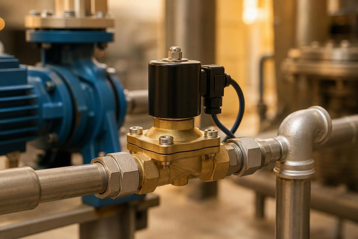
A normally closed solenoid valve is closed when its coil is de-energized and opens when energized under the model’s specified electrical, pressure, flow-direction, and operating conditions. That definition answers one important question: what happens without electrical power? It does not establish whether the valve can pass enough flow, open at the available pressure differential, tolerate the medium, connect to the controller, or satisfy the application’s approvals.
Selection should therefore begin with the required power-loss state. Next, choose an actuation method that works under the system’s actual pressure conditions. Then verify flow capacity, pressure drop, media and seal compatibility, coil requirements, port arrangement, installation limits, and approvals against the current manufacturer datasheet for the complete order code.
What “normally closed” means in each power state
For a conventional normally closed, or NC, solenoid valve, the de-energized position blocks flow. Applying the correct electrical power opens the valve if its other operating requirements are satisfied. Removing power returns a conventional spring-return valve to its closed position (Tameson’s NC and NO valve guide).
| Electrical state | Conventional NC valve state | Expected flow state |
|---|---|---|
| Power off | Closed | Flow blocked within the valve’s leakage specification |
| Power on | Open, provided specified operating conditions are satisfied | Flow permitted |
| Power lost after operation | Returns to closed | Flow stops within the valve’s operating limits |
The word normally refers to the valve’s position when the coil is de-energized. It does not mean that the valve is closed for most of its working life. A valve can be normally closed yet remain energized and open throughout most of a production shift.
A simplified direct-acting example works like this:
- The coil receives its rated voltage.
- Current in the coil produces a magnetic field.
- Magnetic force moves an armature, plunger, or poppet.
- That movement lifts the sealing element and opens the flow path.
- When power is removed, a return spring moves the mechanism back to the closed position.
This spring-and-plunger sequence is a useful model, not a universal description of every internal construction. Diaphragms, pilot passages, pistons, spools, and other arrangements may be involved. The dependable meaning of NC is the de-energized state, not one particular internal mechanism.
A 2/2-way valve has two ports and two positions: open and closed. In a typical two-port NC shutoff valve, one port is upstream, one is downstream, and energizing the coil establishes the flow path. The exact permitted direction still comes from the body marking and datasheet.
They should not be treated as modulating control valves unless the product is explicitly designed and documented for proportional operation. HVAC solenoid stop valves provide one example of this open-or-closed distinction (HVAC Know It All’s solenoid-valve sizing guide).
The practical interpretation is simple: NC tells you the state with no coil power. It does not tell you the number of ports, internal actuation method, capacity, permitted medium, or pressure limits.
Fail closed is a system decision, not a universal safety advantage
Begin with one question:
When electrical power disappears, must flow stop or continue?
An NC valve supplies a fail-closed response only in a limited, positional sense: loss of coil power causes the valve to return to its closed state. Whether that state makes the system safer depends on what the fluid is doing and what hazards arise when it stops.
Fail-closed behavior can be appropriate for water isolation, air or gas shutoff, fuel isolation, dispensing, timed washdown, and leak-limiting duties—provided the complete valve assembly is compatible with the service and carries every approval the application requires. In each case, the intended outage response is to stop flow.
The opposite may be true where continued flow protects equipment or people. Examples include cooling that must continue, lubrication needed during coast-down, ventilation, a bypass path, or a pressure-relief function. An NC valve in one of those paths could remove the protection precisely when electrical power fails. The required response may instead be open flow, venting, pressure equalization, or another documented safe state.
| Selection factor | Normally closed valve | Normally open valve |
|---|---|---|
| De-energized position | Closed | Open |
| Energized position | Open | Closed |
| Power-loss behavior | Returns to closed | Returns to open |
| Coil consumes power while | Held open | Held closed |
| Often considered when | Flow should stop by default | Flow should continue by default |
This comparison assumes conventional monostable valves. Latching or bi-stable valves work differently: they use a brief electrical input to change state and can retain a position without continuous coil power.
Energy use follows the commanded state. A conventional NC valve consumes no coil power while closed but requires power while held open. If a process flows nearly continuously, an NO or bi-stable design may reduce energized time—but only after the correct failure state has been determined. Energy savings must not reverse the intended outage behavior.
Reliability depends on the actual design, medium cleanliness, pressure, temperature, switching rate, electrical supply, installation, and maintenance. The NC label also does not prove tight shutoff or define allowable leakage.
Changing the default state changes system logic. Replacing an NO valve with an NC model can make a line closed at startup instead of open and stop flow during an outage instead of allowing it. NC and NO valves are therefore not normally direct substitutes, even if their voltage and connections match (Electric Solenoid Valves’ NC-versus-NO guide).
Do not confuse default position, port arrangement, and actuation method
Solenoid-valve descriptions answer separate questions:
- NC or NO: What position does the valve assume without coil power?
- 2/2-way, 3/2-way, or another configuration: How many ports and switching positions are provided?
- Direct-acting, semi-direct, or pilot-operated: How does the valve generate the force needed to change state?
- Shutoff, directional, or proportional: What control function does it perform?
These properties are independent. A valve can be normally closed and direct-acting, normally closed and pilot-operated, normally open and direct-acting, or another documented combination. Never infer the actuation method from the normal state.
Two-port NC shutoff valve
A conventional 2/2-way NC valve can be represented as:
DE-ENERGIZED
Inlet ──[ CLOSED ]── Outlet

ENERGIZED
Inlet ──[  OPEN  ]── Outlet
There are two ports and two positions. The valve either interrupts or permits the defined flow path.
Three-port NC directional valve
A conventional NC three-port pneumatic arrangement may have:
- P: pressure or supply
- A: cylinder or actuator
- E: exhaust
Its states can be represented as:
DE-ENERGIZED
P ──X
A ───── E

Pressure is closed.
Actuator port is connected to exhaust.
ENERGIZED
P ───── A
E ──X

Pressure is connected to the actuator port.
The former actuator-to-exhaust connection changes.
That routing is materially different from a two-port shutoff valve. In the conventional three-port arrangement shown above, the pressure, actuator, and exhaust relationships change when the coil is energized (CPV Manufacturing’s three-port valve overview).
Other three-port and multiport arrangements exist. Identify each port from the exact schematic printed on the valve or supplied in its current documentation. Do not infer pressure, actuator, or exhaust routing from “NC,” the casting shape, or the location of threaded connections.
Direct, semi-direct, or pilot-operated: choose by pressure and flow conditions
Once the required de-energized state is settled, determine how the valve can open under the actual pressure conditions.
Direct-acting
A direct-acting valve uses the solenoid mechanism to open the main flow path directly. Magnetic force must overcome the closing force and the relevant process-pressure load on the sealing element, so direct designs are commonly used for smaller orifices and lower flow requirements.
Direct-acting models commonly operate without a minimum differential pressure. That can make a documented zero-differential model worth considering for zero-pressure startup or a circuit in which upstream and downstream pressures may equalize.
Semi-direct
A semi-direct design combines solenoid force with pressure-assisted movement of the main valve. Some models can open from zero differential while providing more capacity than a small direct-acting valve.
“Semi-direct” is a design family, not a universal performance guarantee. Confirm the minimum and maximum differential, opening and closing behavior, permitted backpressure, and flow capacity for the exact model.
Pilot-operated
A pilot-operated valve uses process pressure to help move a larger diaphragm, piston, or main sealing element. Energizing the coil operates a smaller pilot passage; the resulting pressure imbalance opens the main flow path. This can provide greater flow without requiring a coil whose force rises in direct proportion to the main-port size.
The tradeoff is dependence on process conditions. A pilot-operated valve commonly requires a persistent, model-specific differential between inlet and outlet. If that differential is unavailable, the valve may not open, close, or reset as intended.
Published examples show why there is no universal threshold. One general selection guide describes a differential of approximately 0.5 bar for indirect-operated valves (Tameson’s selection guide). An HVAC article specifies 1 psi for the particular pilot-operated valves it discusses. These figures are not interchangeable design rules; the selected valve’s current datasheet controls.
A pilot-operated valve may therefore be a poor fit when:
- the system must open at zero inlet pressure;
- startup occurs before pressure has developed;
- upstream and downstream pressures equalize;
- inlet pressure can fall below the stated operating requirement;
- downstream backpressure removes the necessary differential;
- vacuum operation is required but not documented; or
- gross oversizing produces too little pressure drop for reliable pilot action.
Oversizing is not always harmless. A very large valve may appear attractive because it minimizes restriction, yet the resulting low pressure drop can deprive some pilot mechanisms of the differential they require.
Actuation-method decision flowchart
START
  |
  v
Must the valve open or reset at zero differential pressure?
  |-- YES --> Consider direct-acting or a documented zero-differential
  |           semi-direct design.
  |           |
  |           v
  |        Can it pass the required flow at the allowable pressure drop?
  |           |-- YES --> Verify all remaining limits.
  |           |-- NO  --> Seek a higher-capacity documented zero-differential
  |                       design or revise the system architecture.
  |
  |-- NO --> Determine the minimum differential available during
              startup, normal flow, low inlet pressure, high
              backpressure, shutdown, and restart.
                |
                v
          Is that minimum above the exact pilot valve's requirement
          with an appropriate operating margin?
                |-- NO --> Do not use that pilot-operated model.
                |         Consider direct or semi-direct operation.
                |
                |-- YES --> Size for required flow and allowable pressure drop.
                              |
                              v
                       Does the selected size preserve the differential
                       needed for reliable pilot operation?
                              |-- NO --> Re-size or choose another mechanism.
                              |-- YES --> Verify pressure, media, coil,
                                         leakage, installation, and approvals.
The key input is not merely normal inlet pressure. It is the lowest available differential in every condition in which the valve must change state.
Size for flow and pressure drop—not connection size alone
Before browsing valves, create a service worksheet:
| Service input | Required information |
|---|---|
| Medium | Exact liquid, gas, refrigerant, steam, vacuum service, or other fluid |
| Phase and condition | Liquid, gas, vapor, possible two-phase state, and cleanliness |
| Concentration | Mixture composition or chemical concentration where relevant |
| Temperature | Normal, minimum, maximum, ambient, and media temperature |
| Inlet pressure | Normal, minimum, and maximum |
| Outlet pressure | Normal, minimum, maximum, and possible backpressure |
| Required flow | Minimum, normal, and peak |
| Allowable pressure drop | At each important flow condition |
| Operating sequence | Startup, shutdown, outage, equalization, and cycling frequency |
Nominal port or pipe size describes the connection. It does not establish the internal opening or the amount of flow the valve can pass. Two valves with 1/4-inch NPT ports can have different orifices, body passages, flow coefficients, pressure ratings, and operating mechanisms.
Orifice diameter describes a critical flow opening within the valve. Cv and Kv are flow-capacity coefficients used under different conventions. Under comparable conditions, a higher coefficient generally indicates greater flow for a given pressure drop. Neither connection size nor coefficient alone completes the selection: fluid properties, pressure regime, temperature, compressibility, and phase also matter.
Use manufacturer sizing data or an appropriate engineering method for the actual service. Avoid choosing from a generic pipe-size table when model-specific capacity data are available.
Record these as separate datasheet fields:
- minimum inlet or operating pressure;
- maximum operating pressure;
- minimum differential pressure;
- maximum operating differential or shutoff pressure;
- permitted downstream pressure and backpressure;
- proof or burst data, if relevant and documented;
- leakage specification and test basis;
- response or switching time;
- orifice diameter;
- Cv or Kv; and
- flow direction and any bidirectional rating.
One pressure number cannot substitute for the entire list. “Maximum pressure,” for example, may not state the maximum differential against which the solenoid can open.
The sizing risks run in opposite directions:
- Undersizing can restrict flow, create excessive pressure loss, and reduce delivered capacity.
- Gross oversizing can add cost and bulk and, in some pilot-operated designs, reduce differential pressure enough to cause unreliable operation.
Refrigeration provides a bounded illustration rather than a universal rule. One HVAC example compares valves with the same connection size but materially different capacities and pressure drops. Its figures apply to the stated refrigerant system and valve families, not automatically to water, air, steam, or another refrigerant.
Why identical 1/4-inch connections do not mean identical performance
These commercial listings demonstrate the narrow point that identical nominal connections can accompany different internal specifications:
| Seller-listed field | STC 2S035 retailer example | STC 2W025/040 manufacturer example |
|---|---|---|
| Connection | 1/4-inch NPT | 1/4-inch NPT |
| Body | Stainless steel | Brass |
| Actuation | Direct-acting | Direct-acting |
| Orifice | 3.5 mm | 2.5 mm |
| Cv | 0.5 | 0.25 |
| Listed operating pressure | 0–170 psi | Model-dependent: 0–150 or 0–100 psi |
| Seal choices | NBR or FKM/Viton | NBR; optional FKM/Viton |
These are vendor-provided specifications, not independent test results. They must be confirmed against current documentation for the complete order code. Even so, the comparison establishes the selection principle: a 1/4-inch connection does not guarantee the same orifice, Cv, body, seal, or pressure limit.
Verify materials, seals, coil, duty rating, and enclosure details
Treat valve selection as two linked reviews:
- Wetted mechanical assembly: body, tube, plunger, spring, diaphragm, seals, and every other component exposed to the medium.
- Electrical assembly: coil, connector, cable entry, accessories, controller interface, enclosure, and approvals.
Passing one review does not compensate for failing the other.
Body and seal compatibility
Brass and stainless steel are alternatives, not rungs on a universal good-better-best ladder. Brass may suit one water or air service and be unsuitable for a particular chemical or regulated application. Stainless steel may improve compatibility elsewhere but still be wrong because of the exact alloy, an internal elastomer, temperature, exposure conditions, or a governing rule.
The same caution applies to common seal families:
- NBR or Buna-N
- FKM, often sold under the Viton name
- EPDM
Each has application-specific strengths and limitations. A seal-family name does not establish compatibility on its own. Check the exact medium, concentration, additives, temperature, pressure, exposure duration, cleaning chemicals, and cycling conditions. Check every wetted material, not only the body and main seal.
Steam illustrates the danger of reading too much into a listing. The cited STC examples list steam only conditionally with a Viton seal. That does not establish universal steam suitability for FKM, either valve family, or another product. Steam temperature, pressure, condensate, cycling, installation, and approval requirements still require exact documentation.
Two bounded datasheet-reading examples
The retailer-listed STC 2S035 is described as a 1/4-inch NPT, two-way NC valve with direct actuation, a stainless-steel body, Cv 0.5, NBR or Viton options, multiple AC and DC coil voltages, and a continuous-duty coil. These are examples of fields a buyer should inspect, not independent proof of performance, certification, or current availability.
The STC 2W025/040 specification page describes brass, two-way NC, direct-acting models with a 2.5 mm orifice, Cv 0.25, NBR or optional Viton seals, and model-dependent operating-pressure limits. It also lists a 20 W, continuous-duty, Class H, IP65 coil and several AC and DC voltage options.
The comparison is useful because the products look superficially similar. Yet their capacity, body material, seal choices, electrical variants, and pressure limits differ. Retrieve the current datasheet for the complete order code rather than relying on a series name or an old commercial listing.
Electrical checklist
Confirm every applicable field:
- nominal voltage;
- AC or DC;
- AC frequency;
- permitted voltage tolerance;
- coil wattage;
- AC inrush and holding demand;
- controller, relay, and power-supply capacity;
- connector type and pin arrangement;
- cable and conductor requirements;
- protective grounding;
- polarity requirements;
- polarity-sensitive LEDs, suppression diodes, timers, or rectifiers;
- duty rating and allowed switching frequency;
- insulation class;
- ambient and coil temperature limits;
- ingress-protection rating for the assembled connector and coil;
- hazardous-location or other required approvals; and
- certification scope for the complete valve-and-coil combination.
Do not issue or follow generic instructions such as “DC polarity never matters.” A plain coil may be non-polarized, while a connector containing a diode, LED, timer, or other electronics may require defined polarity. Follow the exact wiring diagram.
It does not mean the coil stays cool or tolerates incorrect voltage, blocked heat dissipation, an incompatible connector, or operation while detached.
The STC 2W025/040 page specifically warns not to energize the cited coil while it is removed from the valve because it may overheat and create a fire hazard. It describes heat after extended energization as expected but calls for immediate power disconnection if there is smoke or a burning odor (STC’s coil specifications and warning). Treat that as product-specific guidance and follow the manual for the model actually installed.
Install and commission the exact model safely
General guidance cannot replace the selected valve’s manual, applicable electrical rules, pressure-system procedures, or application-specific codes. If current documentation is missing, do not improvise from a similar-looking valve.
Pre-installation sequence
Before installation:
- Identify the medium and confirm that the system can be safely removed from service.
- Isolate the pressure source, relieve trapped pressure, and follow the applicable procedure for verifying a safe pressure state.
- Disconnect electrical power and follow the applicable electrical-isolation procedure.
- Confirm the complete valve model, order code, coil voltage, frequency, and connector.
- Identify every port from the valve schematic.
- Confirm the marked flow direction and permitted mounting orientation.
- Inspect the valve, pipework, fittings, and medium for dirt, scale, thread debris, and shipping damage.
- Recheck pressure, temperature, differential, backpressure, materials, filtration, and approvals.
General installation instructions support isolating supply pressure, matching valve and supply voltage, following the marked flow direction, wiring the valve, and cycle-testing it. The exact model manual remains controlling (Valves Online’s installation overview).
Many conventional solenoid valves have a required flow direction, often marked with an arrow. Follow the model’s marking and manual rather than assuming the valve is bidirectional. Reverse installation may prevent the mechanism from operating as specified.
It is not universal. Some products permit other orientations, while others impose specific restrictions.
Wiring and contamination control
Before wiring, confirm:
- supply voltage matches the coil;
- AC frequency is correct;
- the connector pinout matches the diagram;
- protective grounding is provided where required;
- the controller can support the electrical demand; and
- any polarity-sensitive accessory is connected correctly.
Thread-sealing material can become a fault source. Loose tape or sealant may enter a passage or interfere with a moving component. Use only the approved sealing method, keep material out of the flow path, and follow the fitting and valve instructions. Installation guidance for pneumatic valves likewise warns that loose thread-tape debris can enter and jam a valve (VPC Pneumatic’s installation guidance).
Do not add an arbitrary strainer and assume contamination control is complete. Determine the valve manufacturer’s required filtration level, pressure-drop allowance, maintenance interval, and acceptable filter material. Cleanliness measures must suit both the valve and the process.
Controlled commissioning
Where the system procedure and model manual permit:
- Recheck mechanical joints and electrical terminations.
- Pressurize gradually.
- Inspect for external leakage before energizing.
- Energize the coil under controlled conditions.
- Verify the actual flow state rather than relying only on an audible click.
- Confirm opening, closing, pressure drop, and downstream response.
- Cycle the valve through the intended sequence.
- Reinspect for leakage, abnormal noise, connector heating, or unstable operation.
- Document the order code, coil details, measured supply, and test result.
Gradual pressurization, leak inspection, controlled energization, and functional cycle testing appear in general pneumatic-valve installation guidance. Apply them only where consistent with the exact valve manual and the system’s approved commissioning procedure.
Fast closure in a liquid line can create water hammer or another pressure transient. A system-level review is warranted when the line is long, liquid velocity is high, supports are vulnerable, or closure is rapid. Response speed is not automatically beneficial if it creates damaging surge pressure (Tameson’s selection guide).
Verify the complete valve-and-coil assembly, the scope and limitations of each approval, and all installation requirements using current authoritative documentation and appropriately qualified personnel.
Replace or troubleshoot without changing the system’s logic
A replacement must preserve the required function as well as fit the pipe and wiring. Matching voltage, thread size, or exterior dimensions alone is not enough.
Replacement checklist
Compare the existing valve’s nameplate, schematic, manual, and order code with the proposed replacement:
- NC, NO, or bi-stable default state;
- two-way, three-way, or other porting;
- exact port function and schematic;
- direct, semi-direct, or pilot operation;
- permitted flow direction;
- minimum inlet pressure;
- minimum differential pressure;
- maximum operating and shutoff pressure;
- allowable backpressure;
- Cv or Kv and orifice;
- leakage specification;
- response time;
- connection type, size, and thread standard;
- face-to-face and overall dimensions;
- mounting and orientation limits;
- body and all wetted materials;
- seal and diaphragm materials;
- media and temperature limits;
- coil voltage and AC/DC type;
- AC frequency;
- wattage, inrush, and holding demand;
- duty and switching limits;
- connector and pinout;
- enclosure or ingress rating;
- ambient-temperature range; and
- application and hazardous-location approvals.
Replacing NC with NO—or NO with NC—can reverse startup, shutdown, and power-loss behavior even when the new valve screws into the same fittings and accepts the same nominal voltage.
Bounded symptom table
This table is a non-exhaustive starting point for checks against the exact model manual, not a universal repair procedure.
| Symptom | Items to verify |
|---|---|
| Valve does not open | Missing, low, or incorrect voltage; wrong AC frequency; unsuitable coil; connector fault; contamination; pressure outside the opening limit; inadequate differential for a pilot valve; wrong flow direction |
| Valve does not close or leaks internally | Contamination at the seat; damaged or incompatible seals; backpressure outside specification; incorrect flow direction; pressure outside the documented range |
| Valve buzzes or chatters | Incorrect voltage or AC frequency; unstable supply; loose coil or connector; contamination; operating conditions outside the documented pressure range |
| Coil appears unusually hot | Wrong voltage or frequency; ambient temperature outside specification; unsuitable duty; incorrect coil installation; connector fault; operation beyond documented limits |
| Smoke or burning odor | Electrical or thermal fault requiring safe power disconnection and no further energization until the cause is resolved |
| Valve clicks but flow does not change | Blocked line or orifice; wrong port identification; inadequate pilot differential; upstream isolation; incorrect installation direction |
| Intermittent operation | Loose electrical connection, supply-voltage variation, contamination, or changing differential pressure; diagnose against the manual |
Some continuously energized coils become warm or hot in normal service. Acceptability must be judged against the manufacturer’s temperature limits and test conditions—not by touch alone. Smoke or a burning odor is not ordinary operating warmth.
Before inspection, isolate pressure and electrical energy using the applicable procedures and account for trapped fluid, stored pneumatic or hydraulic energy, hot surfaces, hazardous media, and automatic control signals. Do not loosen, remove, or disassemble a valve while it remains pressurized or energized; general installation guidance requires depressurization and electrical disconnection before work begins (VPC Pneumatic’s safety instructions).
Stop work when the medium is unknown, labels are missing, the service is safety-critical, the location is hazardous, or current documentation cannot be obtained. Trial-and-error replacement in those conditions can change system logic or expose personnel and equipment to uncontrolled pressure, electrical energy, chemicals, fire, or heat.
The selection sequence remains the same: decide what flow must do when power is lost, choose an actuation method that works at the available differential pressure, size for actual flow and pressure drop, and verify materials, seals, coil, porting, installation limits, and approvals. The normally closed label answers only the default-state question. The exact current manufacturer datasheet must answer the rest.
Frequently Asked Questions
What happens to a normally closed solenoid valve when power fails?
A conventional NC solenoid valve returns to its de-energized, closed state, stopping the controlled flow within its specified leakage and operating limits. In a simplified spring-return design, removing power eliminates the magnetic force and allows the return spring to reseat the sealing element.
This is “fail closed” only in the positional sense. It is beneficial only if stopping flow is the required system response.
Does a normally closed solenoid valve need pressure to open?
It depends on the actuation method. A direct-acting valve commonly can open without a minimum differential, and some semi-direct designs are documented for zero-differential operation. A pilot-operated valve commonly needs a persistent, model-specific differential between inlet and outlet.
Check startup, low-pressure, equalized-pressure, and backpressure conditions against the exact datasheet rather than applying a generic minimum.
Can a normally closed valve be installed in any direction or orientation?
Not as a general rule. Follow the marked flow direction and the model’s permitted mounting positions. Coil-up or vertical-solenoid mounting is a common recommendation, but some products permit other positions and others impose restrictions. The NC label itself says nothing about flow direction or orientation.
Can I replace a normally open solenoid valve with a normally closed model?
Not as a like-for-like substitution unless the system has been deliberately redesigned and validated for the reversed logic. An NO valve is open without power; an NC valve is closed. The change can reverse startup, shutdown, and outage behavior even if port size, coil voltage, and physical dimensions match.
Is it normal for a continuously energized solenoid coil to become hot?
Some continuous-duty coils become warm or hot while energized. A continuous-duty rating allows extended energization only under the manufacturer’s specified voltage, ambient temperature, installation, and heat-dissipation conditions; it does not mean the coil remains cool.
Disconnect power safely if there is smoke, a burning odor, damaged insulation, or temperature beyond the documented limit.